MRF7S18125BHR3 MRF7S18125BHSR3
1
RF Device Data
Freescale Semiconductor
RF Power Field Effect Transistors
N-Channel Enhancement-Mode Lateral MOSFETs
Designed for GSM and GSM EDGE base station applications with
frequencies from 1800 to 2000 MHz. Can be used in Class AB and Class C for
all typical cellular base station modulations.
GSM Application
?
Typical GSM Performance: VDD
= 28 Volts, I
DQ
= 1100 mA,
Pout
=
125 Watts CW, f = 1930 MHz.
Power Gain ? 16.5 dB
Drain Efficiency ? 55%
GSM EDGE Application
?
Typical GSM EDGE Performance: VDD
= 28 Volts, I
DQ
= 1100 mA,
Pout
= 57 Watts Avg., Full Frequency Band (1930-1990 MHz).
Power Gain ? 17 dB
Drain Efficiency ? 39%
Spectral Regrowth @ 400 kHz Offset = -60 dBc
Spectral Regrowth @ 600 kHz Offset = -74 dBc
EVM ? 2.6% rms
?
Capable of Handling 5:1 VSWR, @ 28 Vdc, 1960 MHz, 125 Watts CW
Output Power
?
Typical Pout
@ 1 dB Compression Point
140 Watts CW
Features
?
Characterized with Series Equivalent Large-Signal Impedance Parameters
?
Internally Matched for Ease of Use
?
Integrated ESD Protection
?
RoHS Compliant
?
In Tape and Reel. R3 Suffix = 250 Units per 56 mm, 13 inch Reel.
Table 1. Maximum Ratings
Rating
Symbol
Value
Unit
Drain-Source Voltage
VDSS
-0.5, +65
Vdc
Gate-Source Voltage
VGS
-6.0, +10
Vdc
Operating Voltage
VDD
32, +0
Vdc
Storage Temperature Range
Tstg
- 65 to +150
°C
Case Operating Temperature
TC
150
°C
Operating Junction Temperature (1,2)
TJ
225
°C
Table 2. Thermal Characteristics
Characteristic
Symbol
Value (2,3)
Unit
Thermal Resistance, Junction to Case
Case Temperature 81°C, 125 W CW
Case Temperature 81°C, 71 W CW
RθJC
0.31
0.35
°C/W
1. Continuous use at maximum temperature will affect MTTF.
2. MTTF calculator available at http://www.freescale.com/rf. Select Software & Tools/Development Tools/Calculators to access MTTF
calculators by product.
3. Refer to AN1955, Thermal Measurement Methodology of RF Power Amplifiers. Go to http://www.freescale.com/rf.
Select Documentation/Application Notes - AN1955.
Document Number: MRF7S18125BH
Rev. 0, 11/2008
Freescale Semiconductor
Technical Data
MRF7S18125BHR3
MRF7S18125BHSR3
1930-1990 MHz, 125 W CW, 28 V
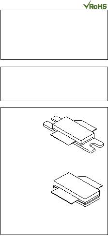
GSM, GSM EDGE
LATERAL N-CHANNEL
RF POWER MOSFETs
CASE 465-06, STYLE 1
NI-780
MRF7S18125BHR3
CASE 465A-06, STYLE 1
NI-780S
MRF7S18125BHSR3
?
Freescale Semiconductor, Inc., 2008. All rights reserved.


发布紧急采购,3分钟左右您将得到回复。
相关PDF资料
MRF7S18170HSR5
MOSFET RF N-CH NI-880S
MRF7S19080HSR5
MOSFET RF N-CH NI-780S
MRF7S19100NR1
MOSFET RF N-CH 28V 29W TO270-4
MRF7S19120NR1
MOSFET RF N-CH TO-270-4
MRF7S19170HSR5
IC MOSFET RF N-CHAN NI-880S
MRF7S19210HSR5
MOSFET RF N-CH 28V 63W NI780S
MRF7S21080HSR5
MOSFET RF N-CH 22W NI-780S
MRF7S21110HSR5
MOSFET RF N-CH 33W NI-780S
相关代理商/技术参数
MRF7S18170H
制造商:FREESCALE 制造商全称:Freescale Semiconductor, Inc 功能描述:RF Power Field Effect Transistors (N-Channel Enhancement-Mode Lateral MOSFETs)
MRF7S18170HR3
功能描述:射频MOSFET电源晶体管 1.8GHZ HV7 WCDMA NI880H RoHS:否 制造商:Freescale Semiconductor 配置:Single 晶体管极性: 频率:1800 MHz to 2000 MHz 增益:27 dB 输出功率:100 W 汲极/源极击穿电压: 漏极连续电流: 闸/源击穿电压: 最大工作温度: 封装 / 箱体:NI-780-4 封装:Tray
MRF7S18170HR5
功能描述:射频MOSFET电源晶体管 1.8GHZ HV7 WCDMA NI880H RoHS:否 制造商:Freescale Semiconductor 配置:Single 晶体管极性: 频率:1800 MHz to 2000 MHz 增益:27 dB 输出功率:100 W 汲极/源极击穿电压: 漏极连续电流: 闸/源击穿电压: 最大工作温度: 封装 / 箱体:NI-780-4 封装:Tray
MRF7S18170HSR3
功能描述:射频MOSFET电源晶体管 HV7 1.8GHZ 50W RoHS:否 制造商:Freescale Semiconductor 配置:Single 晶体管极性: 频率:1800 MHz to 2000 MHz 增益:27 dB 输出功率:100 W 汲极/源极击穿电压: 漏极连续电流: 闸/源击穿电压: 最大工作温度: 封装 / 箱体:NI-780-4 封装:Tray
MRF7S18170HSR5
功能描述:射频MOSFET电源晶体管 HV7 1.8GHZ 50W RoHS:否 制造商:Freescale Semiconductor 配置:Single 晶体管极性: 频率:1800 MHz to 2000 MHz 增益:27 dB 输出功率:100 W 汲极/源极击穿电压: 漏极连续电流: 闸/源击穿电压: 最大工作温度: 封装 / 箱体:NI-780-4 封装:Tray
MRF7S19080HR3
功能描述:射频MOSFET电源晶体管 HV7 1.9GHZ 28V RoHS:否 制造商:Freescale Semiconductor 配置:Single 晶体管极性: 频率:1800 MHz to 2000 MHz 增益:27 dB 输出功率:100 W 汲极/源极击穿电压: 漏极连续电流: 闸/源击穿电压: 最大工作温度: 封装 / 箱体:NI-780-4 封装:Tray
MRF7S19080HR5
功能描述:射频MOSFET电源晶体管 HV7 1.9GHZ 28V RoHS:否 制造商:Freescale Semiconductor 配置:Single 晶体管极性: 频率:1800 MHz to 2000 MHz 增益:27 dB 输出功率:100 W 汲极/源极击穿电压: 漏极连续电流: 闸/源击穿电压: 最大工作温度: 封装 / 箱体:NI-780-4 封装:Tray
MRF7S19080HS
制造商:Freescale Semiconductor 功能描述:
